
Wiring A Single-Pole Light Switch – DIY Guide
Wiring a single-pole switch is straightforward for pretty much anyone with some home repair experience. It involves connecting two wires to brass screws on the side of the switch and connecting a ground wire to the green screw on the side of the switch.
Tools You Will Need To Wire A Single Pole Switch
- Pliers
- Flathead screwdriver
- Phillips screwdriver
- Voltage Tester
- Able Tip
- Turn off the electrical feed to the switch before exposing electrical wires when removing the switch from the box.
- A non-contact voltage tester is a great way to test electrical power at the switch without touching any exposed wires.
- A good practice is to try the non-contact voltage tester on an electrical wire you know is electrified to ensure the non-contact voltage tester is working correctly.
History Of The Single-Pole Switch
Although single-pole electrical switches have been around since Thomas Edison started working with electricity, did you know that John Henry Holmes was the actual inventor of the single pole switch?
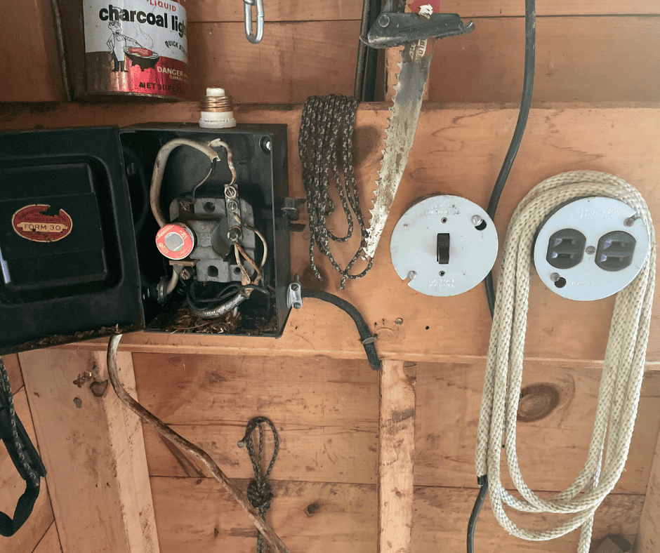
The first electrical switches were the knife switch that you might be familiar with from old Frankenstein movies. These knife switches were used to turn the power on and off by moving the lever holding the copper knife switches into the opposing jaws to connect a circuit.
When electricity was introduced to residential homes, individual wires ran through the house. The first electrification of homes used a wiring method known as knob-and-tube wiring, and many of the first electrical light fixtures replaced gas lights in city homes.
Single-Pole Switch Colors
Today, electrical light switches come in various designs and colors, with the most common being the standard single-pole switch and the Decora style switch. These switches come in these four classic colors; brown, ivory, light almond, and white, with white and light almond being the most common colors used today.
Different Switch Designs And Uses
There are many switch designs from the single-pole switch, double-pole switch, three-pole switch, three-way switch, and four-way switch. Most homes utilize the single pole switch, three-way switch, and sometimes the four-way switch.
- A single pole switch controls an electrical light/s or device/s from one location.
- The three-way switch controls an electrical light or device from two locations.
- And the four-way switch is used between the three-way switches to control electrical lighting from three or even more locations.
You can utilize the four-way switch to control hallway lighting to ten or even more rooms off a hallway so someone can turn on and off lighting from each room location no matter where they are along the hallway.
Dimmer Switch
Dimmer switches get wired just like the single-pole switch. In some cases, dimmer switches will come as a combination switch to be used as a single-pole switch or wired as a three-way switch.
You can tell if it is a combination switch if it has three brass scews on the side of the switch. Follow the directions that come with the dimmer switch for the proper wire connections.
Other Switch Uses
Electrical switches are used to control other electrical things in the home other than just lighting. Electrical switches are used to control electrical outlets, pumps, heating, air conditioning equipment, and other electrical-powered items around the house. No matter the switch design used, they all function and wire similarly.
Need Help On Your Home Improvement Project?
Get started now and request a FREE no-obligation Estimate Today from our Members.
Single-Pole Switch Operation
You can wire or replace any light switch if you understand the fundamentals of their operation and the best wiring practices used today. You only have to familiarize yourself with a couple of wires along with a ground to wire a single pole switch.
The single pole switch interrupts the current-carrying wire to the light fixture, so when they are connected, the light is on, and when they are separated, the light is off.
Another way to look at it and how an electrician would refer to this function; when the switch is closed, the light is on, and when the switch is open, the switch is off.
Single-Pole Switches Have Many Uses
Single-pole switches are used for many electrical applications such as turning on and off lighting, electrical outlets, garbage disposals, and other electrical appliances. Single-pole switches are also used as a service switch for appliances to disconnect the power during servicing.
How A Single-Pole Switch Operates
The single-pole switch is the most straightforward and typical switch used in the home. The switch operates by flipping a lever or toggle up and down to energize and de-energize a circuit.
Understanding The Single-Pole Switch Electrical Circuit
Before doing any wiring, it is important to understand how electrical circuits are wired, so you’ll have a better understanding and know what you’re looking at when you go to wire the single pole switch.
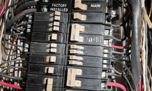
When a house gets wired, electricians run cable known as Romex wire throughout the house for lighting and power. They run the Romex from the main electrical circuit breaker box to all electrical outlets, switch boxes, and any other box needing an electrical feed.
Feeder vs. Switch Leg And The Electrical Code
The current Electrical Code requires that the electrical feed starts at the switch box; however, you might find the electrical feed at the ceiling light outlet box. Back in the day, electricians would run a Romex feed to the ceiling light and run a Romex down to the switch. You’ll know right away if this is the case if you only have one cable in a switch box.
Wiring Terms
In any event, all the terms apply for this and all wiring methods. And knowing the terms helps understand how it all goes together.
As you can probably guess, there is a “feeder”; this is the wire coming from the electrical panel. It is also called the “hot” wire since it is an uninterrupted electrified wire.
The wire that goes to the light is called the “switch leg.” This wire gets interrupted by the single-pole switch.
Romex wire is a cable that has more than two wires. You will find a black, white, and bare wire inside the Romex cable. If the feed is at the switch location, the black wire is the “feeder” or “hot” wire, the other black wire going to the light is the “switch leg,” the white wires are the “neutral” wire, and the bare wire is the ground wire.
To make it a bit more interesting, when the feed is at the light outlet, and there is one cable at the switch outlet, the terms for the wires change.
To signify that the cable is a switch leg with a feeder at the light, electricians use the white wire as the “feeder” or “hot” wire and the black wire as the “switch leg.”
This wiring method may seem to be a little confusing at first, but if you do a few light fixture changes, you’ll understand why when you come across a light outlet box with several feeders. You’ll be able to identify the switch leg cable right away.
When you wire switches using a switch leg with the feed at the light, and the white wire is the “feeder” – “hot” wire, you can mark the white wire with a black sharpie, or use black electrical tape to indicate that the white wire is a “feeder” – “hot” wire.
- Able Tip
Stripping The Insulation – The Proper Length
- A good length of insulation to strip for making electrical connections under screws is to have about 3/4″ of an inch of bare wire.
- Strip the wire using wire strippers and pliers to make a little hook. It’s easier to strip and make all your hooks before attaching them to the switch because you will find the switch in the way.
Connecting wires to screw terminals
- The best way to connect wires to terminal screws is to go around the screw clockwise because when you tighten the screw, you turn it clockwise, right to tight, left to loosen. The wire will be pulled around the screw when you tighten it up.
Where To Connect The “Hot” Wire
- Although installing the “feeder” – “hot” wire to the top screw on the single-pole switch is good practice, it is not a requirement.
- Industry-standard has the feed on the top of a disconnect switch, so an electrician knows where the feed is when they open the switch to live components. And many electricians do this on single-pole switches too.
Connecting the Wires To The Single-Pole Switch
Whether you use a standard or Decora-style single-pole switch, the function and electrical connections are the same. Both types of single-pole switches have brass side screws where you connect the “feeder” or “hot” wire to one screw and the other wire, the “switch leg,” to the other screw. If you want to impress someone, call those screws; “terminals.”
Grounding The Single-Pole Switch
Switches also need to be grounded to the electrical wiring using the bare wire from the Romex. Grounding the switch is a straightforward step if a ground wire is in the switch box with the switch.
New switches will have a green screw attached to the mounting plate of the switch for the ground wire. Connect the ground wire to this screw to ground the switch’s metal mounting plate.
If you are replacing an older switch that does not have a ground screw, but the Romex has a ground wire, you can easily add a bare wire to the Romex’s ground/s using a wire connector such as a wire nut.
Grounding the electrical box with the bare wire is only required if the electrical box is metal. And, if the electrical box is metal, use a green grounding screw to attach the bare wire to the electrical box.
- Able Tip
Pigtail Connections
- Electricians call a group of wire connections a “pigtail.” A pigtail is when a couple or several wires are connected together using a wire connector like a wire nut. There will often be more than one Romex in a box where the wires need to feed other locations; this is when a pigtail is used to distribute the electrical power.